Introduction
The Motherboard is located inside the device. It controls most of the parts in the device like the speakers, ladybug button, and light bulb.
-
-
Locate the battery housing on the back of the flashlight as pictured.
-
Unscrew the single 8 mm Phillips #1 screw.
-
Lift the battery housing cover to reveal the battery terminals. Remove the batteries.
-
-
-
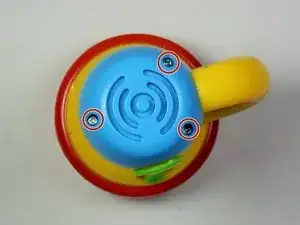
Locate the light blue speaker housing on the bottom of the flashlight.
-
Remove the three 6 mm Phillips #0 screws.
-
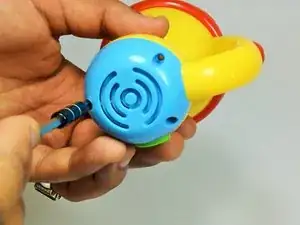
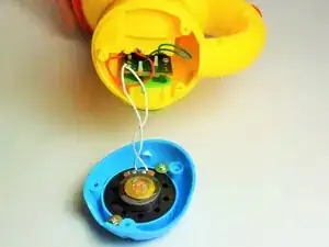
Once the screws have been removed, pull the housing away from the yellow body of the flashlight. Be careful not to disconnect the white wires from the speaker, unless speaker replacement is required.
-
-
-
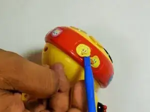
Locate the screw covering stickers on the side of the red ring. These two stickers will be slightly larger than the normal stickers. In this case it was a ladybug and a duck on opposite sides of the ring.
-
With a plastic opening tool, gently remove the stickers by prying around the edges. Be careful with these as you will want to reapply them later
-
-
-
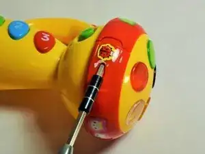
Remove the two 8mm Phillips #0 screws from the screw channels found under the stickers in step one. This can be seen in the first photo if step 2.
-
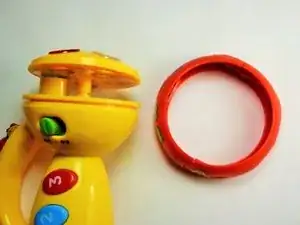
Once the screws have been successfully removed, grasp one half of the ring and pull gently to separate it from the yellow housing. Repeat on the opposite side and the ring is disassembled.
-
-
-
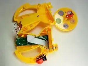
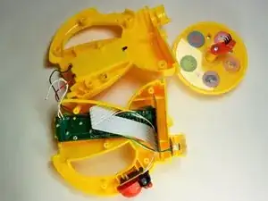
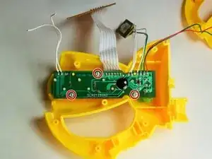
Unscrew the six 8 mm Phillips #0 screws at each of the points circled in red in the first image.
-
To open, separate the two sides of the housing. They should come apart fairly easily, however you may use a spudger to pry it open. Once it's apart, it should look like the second image.
-
-
-
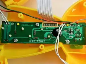
Next, locate the 3 6mm Phillips #0 screws highlighted in the 2nd image, and remove them, using a counterclockwise motion.
-
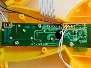
Desolder the 6 wire connections highlighted in the third image. If needed, use iFixit's guide to help desolder the wires. Once these wires have been removed, the main connectors are off, and we can continue to step 2.
-
-
-
Now that the main wires and connectors have been removed, its time to disconnect the smaller wire sets.
-
Desolder the two wires shown in the highlighted rectangle. Pull the wires free and they are disconnected.
-
Lastly, desolder the group of 6 wires in the orange highlighted rectangle. The wire group should consist of 3 white, 1 red, and 2 green wires. Once removed, the motherboard should be free to be replaced.
-


To reassemble your device, follow these instructions in reverse order.