Introduction

  1. ZTN1owbLfeNQMiUW
    ZTN1owbLfeNQMiUW
    OSZw3JoZxIJmdrAW
    • Remove the 2 screws on the back cover using a Phillips head #0 screwdriver.

  2. tBEh21jPI6ORarab
    tBEh21jPI6ORarab
    OUShLBbeWJRYNETm
    • Remove the screw on each side of the device using a Phillips head screwdriver.

  3. OQiVCVmjykmc3pNe
    OQiVCVmjykmc3pNe
    sqapc32WTp5VMskK
    COO6BMPOhbDNa4PI
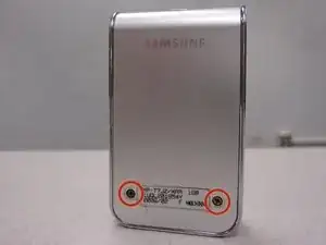
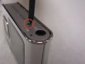
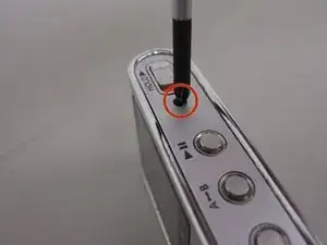
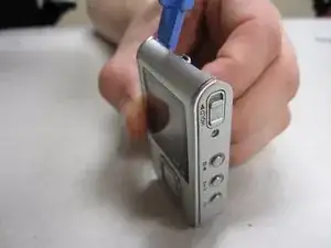
    • Using the plastic opening kit, place the prying end of the kit into the opening created by removing the screws.

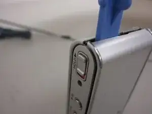
    • Gently pry open the back cover. Insert the plastic opening tool in between the cover joints.

  4. dSJR4WETQ1s4UYeQ
    dSJR4WETQ1s4UYeQ
    XZELkCALcN3SKvnX
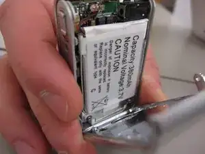
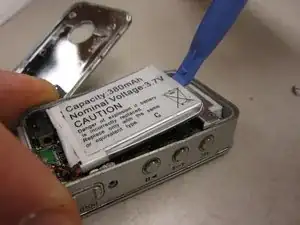
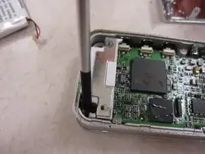
    • Once the back cover has been removed the battery will be visible.

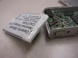
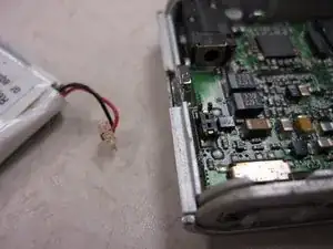
    • Pry the battery from the device.

    • NOTE: The battery should still be connected to the device

  5. uWJvRXvNXQmkgkAS
    uWJvRXvNXQmkgkAS
    sJZUXUBAOEEHkSNG
    • Unplug the battery connecting cables.

    • NOTE: The battery now should be free from all connections to the device.

  6. JceMbjc2mfRUT5t5
    JceMbjc2mfRUT5t5
    r4QUsCeFoOJsRvPh
    mEsuBsAJqmgGxRI2
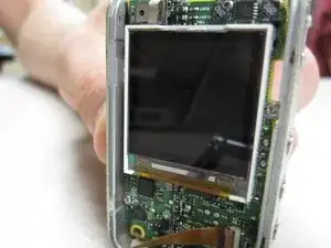
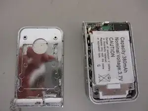
    • Once the battery has been removed you can see the motherboard.

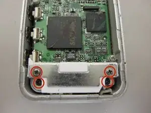
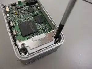
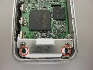
    • Unscrew 4 screws on the metal docket using a Phillips head screw driver.

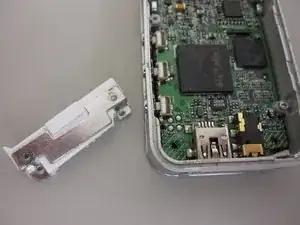
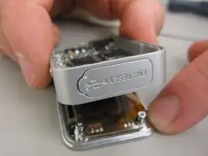
    • The USB connector can now be taken off of the device.

  7. pKotRltwftHlS6Dw
    pKotRltwftHlS6Dw
    J5eYGVn3VrfDFGRN
    • Using the philips screwdriver, remove the two screws on the mother board.

  8. BrssQpYN2bQoAPkw
    BrssQpYN2bQoAPkw
    PgVFGPcFTSI1VXFD
    T4OqVNyFP6ISJwwM
    • Place the pry tool in-between the front cover and mother board.

    • Gently separate the front cover.

  9. a5msKJhqpFLOlVAt
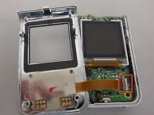
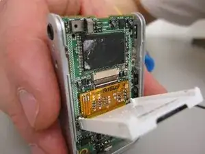
    • After opening the front cover you will see and electric ribbon connecting the buttons to the mother board.

  10. AJcVvBWDcVOUdNFS
    AJcVvBWDcVOUdNFS
    uwUGnVyR4RTjtKSA
    • CAUTION: Do not rip the electric ribbon from the mother board.

    • Carefully flip up the plastic lip that holds the electric ribbon to the board.

  11. odmJg142JjP2Uk6X
    odmJg142JjP2Uk6X
    pTAjLNCQ5jEI4hOC
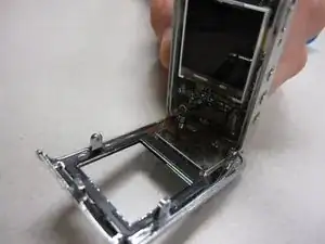
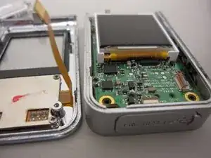
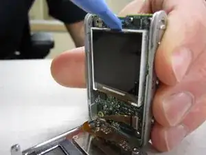
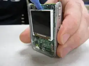
    • Place the pry tool between the plastic housing around the LCD screen, and the mother board.

    • Gently separate the screen housing from the mother board

    • CAUTION: The screen is still attached to the mother board via another electric ribbon.

  12. yR6vxAX2K2nfqdqA
    yR6vxAX2K2nfqdqA
    oBUf4ES5tLCwyICM
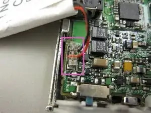
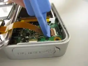
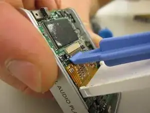
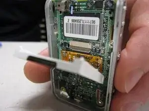
    • Using a plastic pry tool to flip up the lip, which connects the electric ribbon to the mother board.

  13. c3XdOwAgtiR4iLUj
    c3XdOwAgtiR4iLUj
    Vfb4EIONK6eToKED
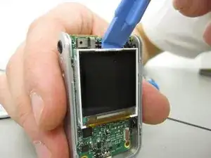
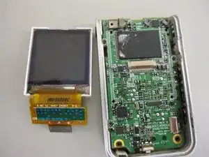
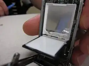
    • Place the pry tool between the LCD screen and the white housing unit

    • Gently separate the two.

  14. cBte5aAvkicr46dm
    cBte5aAvkicr46dm
    FaDSvtx2I33wogGb
    • Insert the new screen into the white unit.

    • Connect the LCD screen to the mother board by inserting the electric ribbon into its port, and closing the lip.

Conclusion

To reassemble your device, follow these instructions in reverse order.

Jason Farr

Member since: 21/10/13

353 Reputation

0 comments