Introduction

This guide will help you disconnect and replace the rear panel connectors of the speaker.

  1. QIXiWpZdDQdBRSLx
    QIXiWpZdDQdBRSLx
    T2srHkvyOwBELHkv
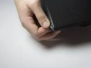
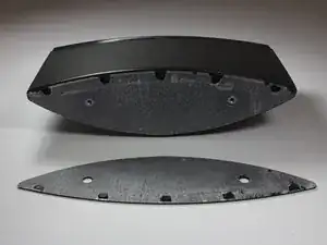
    • Use a spudger or your fingers to pry off and remove the rubber pad on the bottom of the speaker.

  2. IHKPqK46J4iFvkis
    IHKPqK46J4iFvkis
    AY2SZVIxZfd2bUAl
    IJdHEdDmFBEjxv3L
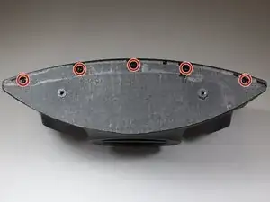
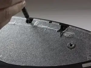
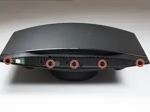
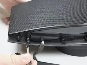
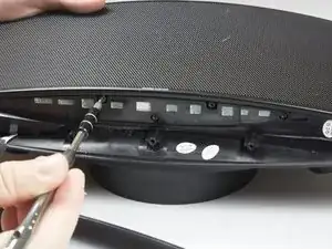
    • Remove the five 10mm screws with a TR 10 screwdriver.

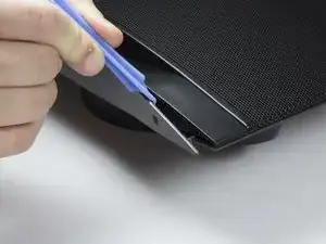
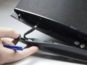
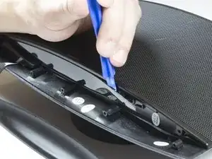
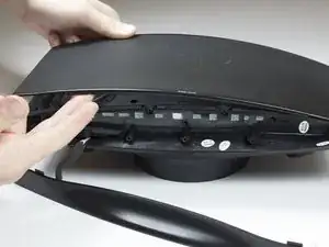
    • Use a spudger to break the remaining adhesive holding the grille to the speaker body.

    • Be sure you don't bend the grille; it is not free from the speaker yet.

  3. jyOiHYB3OJKLNSeG
    • Flip speaker around and use a plastic opening tool to remove the top panel from the speaker.

  4. 4EWibNA5tOYEoDCP
    4EWibNA5tOYEoDCP
    DvVkADKrjYQjKK2h
    rQSGuaQH5H5kSYDg
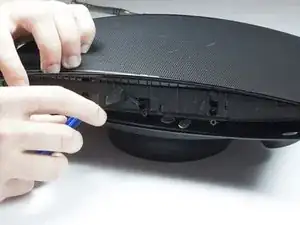
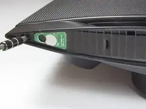
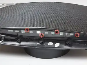
    • Use a plastic opening tool to remove the foam and uncover four more screws.

    • Use a TR 10 screwdriver to remove the five 10mm screws on the top of the speaker.

  5. 1KuEQGAvOqFFHtyk
    1KuEQGAvOqFFHtyk
    DQAvQLLW2EGxUP2B
    • Carefully remove the top cover.

    • Be careful not to tear or stress the cable that provides power to the power LED.

  6. RBiRFnm6QTGXodOW
    RBiRFnm6QTGXodOW
    VKijPkQPwlTqckBx
    • Use a TR 10 screwdriver to remove two of the 10mm screws that secure the speaker grille.

    • Do not attempt to remove the grille just yet.

  7. XruVTAhVdsoHVNEZ
    XruVTAhVdsoHVNEZ
    gLPe56K1qDmXwXjt
    DvJWnOWybuTpNPSG
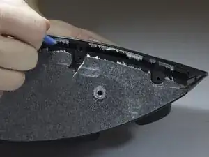
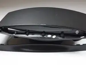
    • With the top panel removed, use a spudger to remove the display panel.

    • The clips on the display panel are quite fragile. Pry up both edges of the display before attempting removal.

    • Use a TR 10 screwdriver to remove the four final 10mm screws securing the speaker grille.

  8. i1wFlIOCQUJOQ6nj
    • Remove the front speaker grille.

  9. hnGDuKohLDToVuti
    hnGDuKohLDToVuti
    xUx56YKMkvyCUEfS
    hUgSPNEuLJO1wD5H
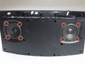
    • After removing grille, you will see the speakers.

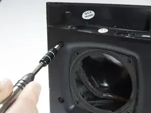
    • Remove the eight 10mm screws that surround the speakers. There will be four around each speaker.

  10. Onvni4WhYGSQubYh
    Onvni4WhYGSQubYh
    wQKIINFHQWLyOEOg
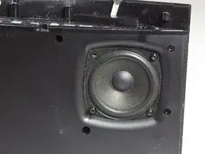
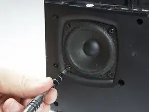
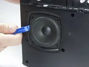
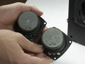
    • Carefully lift each speaker from the housing. It may be necessary to break a light adhesive seal.

    • Be aware of the two wires that are connected to each speaker.

    • Set each speaker beside the main housing.

  11. kYf43kWvg4YFlcyn
    kYf43kWvg4YFlcyn
    QAPTQoiQlrqUteDt
    JrdGBjiB4upykKpJ
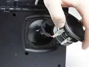
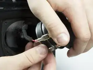
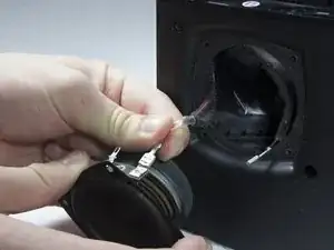
    • Carefully but firmly unplug the two wires from each driver.

    • The front speakers can now be removed.

  12. HZq6XMDQU6ECZnUa
    HZq6XMDQU6ECZnUa
    d2ZK1p1LWbHUJdm3
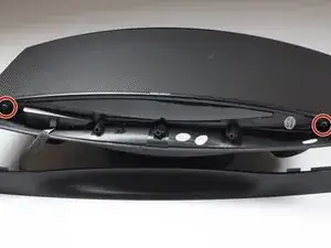
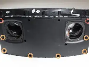
    • Identify the eight screws around the border of the front panel.

    • Using the TR 10 driver, remove the two 8mm screws.

    • Using the TR 10 driver, remove the six 12mm screws.

  13. 1dYSU5RAuUGJwqKe
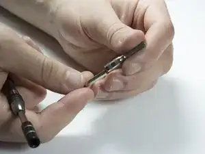
    • Use a 5 mm hex driver to extend the TR 10 driver. This allows the driver to access screws with deeper countersinks.

  14. CaCvERs1JDLqHhHW
    CaCvERs1JDLqHhHW
    bhFpKVyof3TmNWft
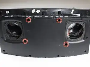
    • Identify the remaining four screws in the front panel.

    • Use the extended driver from the previous step to remove the four 12mm TR 10 screws.

  15. Ku4LF3mW5VEfwWFO
    Ku4LF3mW5VEfwWFO
    xgfQjQYVrJEWPNE3
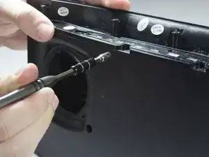
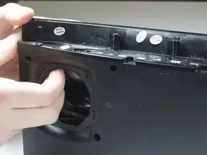
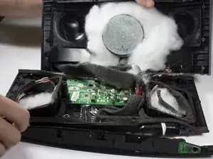
    • Gently pull the front panel away from the back panel.

    • There are wires that connect the front and back panels. The two sides can be safely folded away from each other and laid flat on the table.

    • Remove the white sound dampening material from the speaker. Note the location of the material and set aside.

  16. GZNR1cHAnfs1WIjd
    GZNR1cHAnfs1WIjd
    yZUQvI35j3KWOYuF
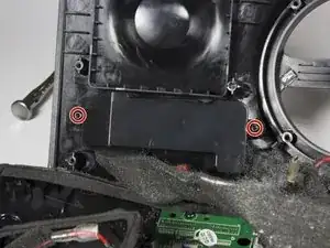
    • Use a TR 10 driver to remove the two 10mm screws securing the connector housing.

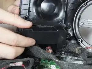
    • Remove the housing from the rear panel.

    • Do not stress or tear the cables that connect this part to the logic board.

  17. eOGhQaXc5tOmweTT
    eOGhQaXc5tOmweTT
    poWVFkD4OMUNqXG2
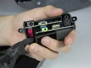
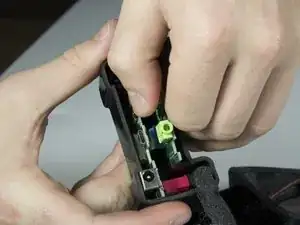
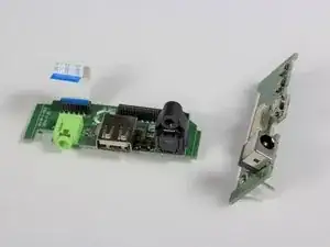
    • With the housing free from the speaker, the two daughterboards can be seen in the housing.

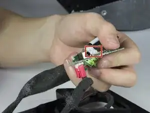
    • Gently remove both boards from the housing.

    • Be aware of the fragile ribbon connector that runs between the boards, as well as the cords that run to the logic board.

  18. IlQcmeaxgcWffIZh
    IlQcmeaxgcWffIZh
    1oQbtIFHBFNoC3KF
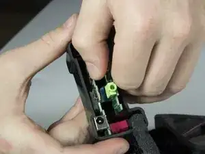
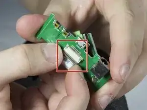
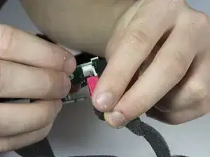
    • Unplug the ribbon cable that connects the daughterboards from the top board. Leave the cable connected to the bottom board.

    • In order to remove the ribbon cable, gently pull the brown retention mechanism away from the connector. The ribbon cable can then be freely removed.

  19. YBUvqul2wxcvHdNA
    YBUvqul2wxcvHdNA
    awqEeCOYfOWiPLES
    • Gently unplug the red power connector from the top daughterboard.

    • Note the correct orientation of this connector for reassembly.

  20. Mqe2c4GhhNGyApEh
    Mqe2c4GhhNGyApEh
    pQtb4ZUhpn6hEQra
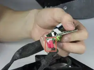
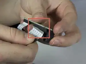
    • Gently pull out the large ribbon cable from the bottom logic board. Grasp the cable as close to the connector as possible and pull it straight away from the board.

    • There is no retention mechanism on this connector.

Conclusion

To reassemble your device, follow these instructions in reverse order.

Shaw Hughes

Member since: 31/01/17

831 Reputation

0 comments