Introduction
To complete this guide, you will need to disassemble your device and use a soldering iron to replace the jack.
-
-
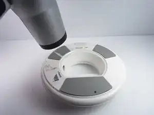
Use a heat gun (set to low) to apply heat to one of the rubber pads until you can easily remove the pad. This step takes around 5-7 minutes.
-
-
-
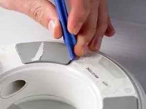
Remove the heated rubber pad with a plastic opening tool.
-
Repeat steps 2 and 3 for the two remaining rubber pads.
-
-
-
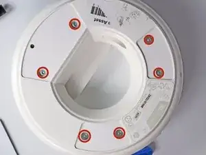
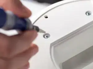
Remove the six 1cm T-10 torx screws on the bottom of the device (found under the rubber pads) using a T-10 Torx screwdriver.
-
-
-
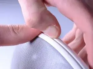
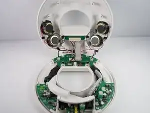
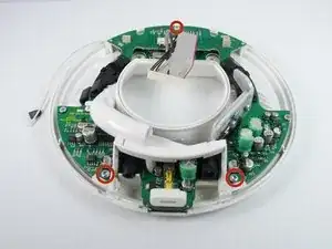
Disconnect the ribbon cable connector from the top half of the device by pulling outward and parallel to the connecting pins.
-
-
-
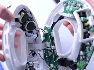
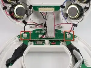
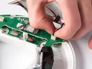
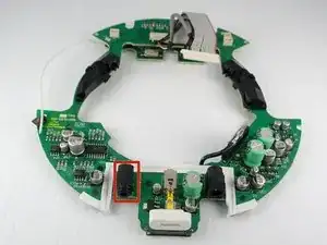
Locate and disconnect the two molex connectors found on either side of the ribbon cable connector on the bottom half of the device.
-
-
-
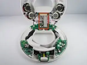
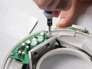
Unbolt the heatsink with a 5.5-mm socket and a Phillips PH1 screwdriver.
-
Remove the heat sink; it should detach from the bottom of the device.
-
-
-
Remove the T-10 torx screw on the bottom of the device that attaches the base tube to the circuit board.
-
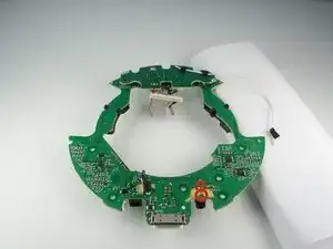
Turn the device so that the base tube is on top.
-
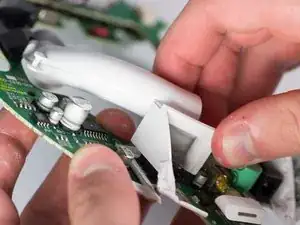
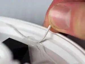
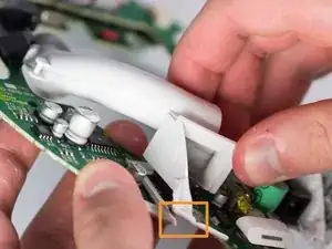
Remove the base tube by pulling up.
-
May need to cut the rubber adhesive between the base tube to the circuit board.
-
-
-
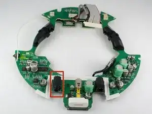
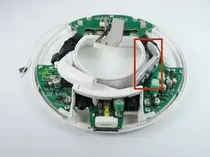
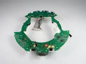
Turn the device upside down.
-
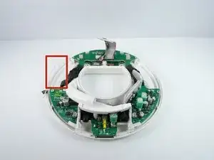
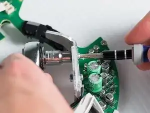
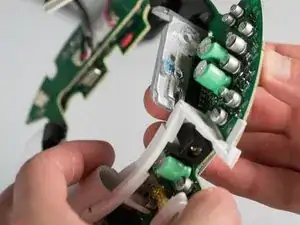
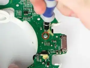
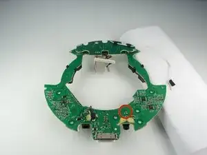
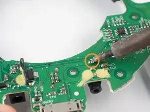
Desolder the back lead for the auxiliary port that is circled.
-
Heat the lead until the solder melts.
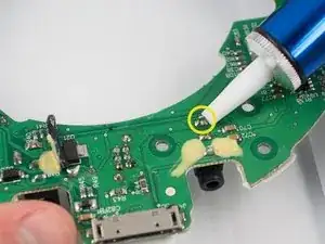
-
Remove the solder with the solder pump.
-
For help with soldering view the iFixit soldering guide
-
To reassemble your device, replace the auxiliary jack with a new one soldering it in place. Follow these instructions in reverse order.