Introduction

Use this guide to replace the motherboard from the computer. Take proper precautions to prevent risk of electrical shock. Be gentle with computer components to prevent accidental damage to fragile parts.

  1. A6UQHIrDj2vWgTOk
    • Make sure to shut down the computer! Go to the start menu and click shutdown from the power options first

    • Ensure all cables, speakers and other devices are unplugged and turned off before opening the computer case.

  2. oTZkgPO3OQAuqh4c
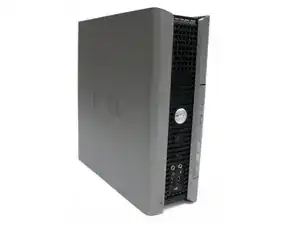
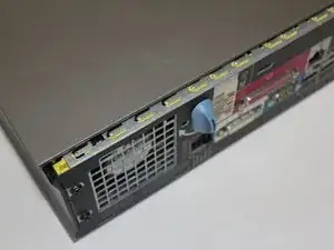
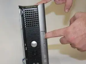
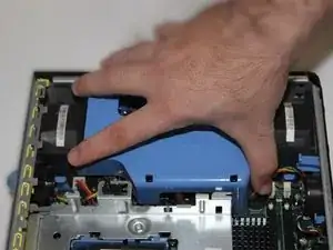
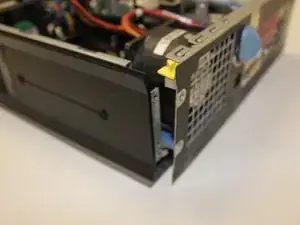
    • Lay the computer on its side; you will see a blue knob.

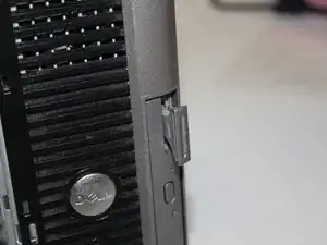
    • Turn said knob 90 degrees counter clockwise.

  3. CMVZX3rIZAU3DwJX
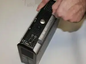
    • While the knob is still turned, slide the panel case forward about 1/2 inch, and then lift the panel off the computer.

  4. qMBiCwAUZZViylBZ
    qMBiCwAUZZViylBZ
    qFFWZNp4shMpHfsh
    • Ground yourself to avoid static from damaging any components. Either use a wrist strap and antistatic mat, or touch the metal computer case every few minutes.

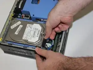
    • Find the power and data cables connected to the hard drive, press down on the metal tab and carefully remove them.

  5. TpE3lONZIHJVaFk3
    TpE3lONZIHJVaFk3
    6RHBXVa4mVSJnrxm
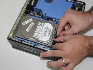
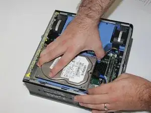
    • Locate the blue tabs shown on the left and right of the hard disk drive

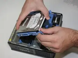
    • Squeeze both tabs and slide the hard disk drive towards you, then lift the drive out of the cage.

  6. aXH6VOUaOTOCifr4
    • Press down on the two white tabs on either side of the memory module; the RAM will pop out.

    • Be sure you are grounded to avoid electrostatic discharge, and place your memory modules in an anti-static bag.

    • Make sure the notch in the RAM lines up with the notch in the slot. It should enter the slot with minimal force. If it does not enter the slot, check that you have the RAM lined up properly.

  7. SXFwpx1HQWTFqw6P
    SXFwpx1HQWTFqw6P
    XYRjmrVRlXiXKG41
    tIiAsiqVBdSoYWFG
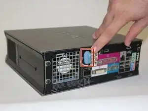
    • Press the large button on the corner of the optical drive. Pull on the pop-out button to slide the optical drive out.

  8. FgallEyVqJmxPGXj
    FgallEyVqJmxPGXj
    6HXLMFNWP26GpJeg
    • Remove the blue shield by sliding it straight upwards.

  9. 3a6MOL26GN1jU61N
    3a6MOL26GN1jU61N
    lSQdMXVTKM6OA1BS
    XtI6sNZstOmdF54w
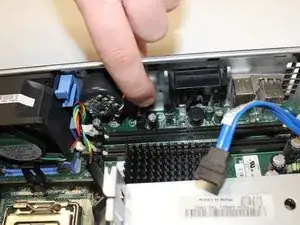
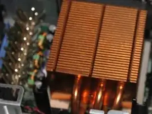
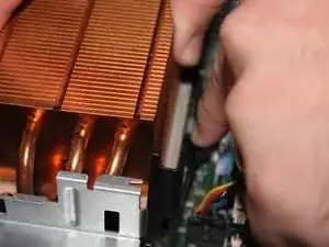
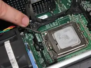
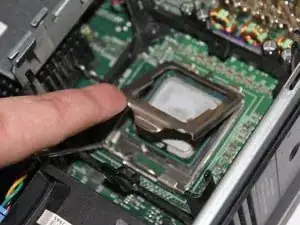
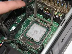
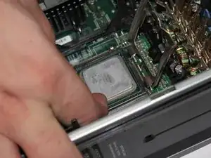
    • Pull back on the tab nearest to the front case fan.

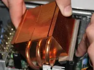
    • Slide the CPU heat sink from under the clip and pull upward.

    • You may need to twist the CPU heat sink side to side to free it from the thermal paste.

  10. LqMXyCx2gq16kdWw
    LqMXyCx2gq16kdWw
    LUIvB43IoRfSFh6J
    • Ground yourself before removing any internal components.

    • Push release lever down slightly and away from CPU.

  11. AE41GEIoOMkCDrxx
    AE41GEIoOMkCDrxx
    vRiSEF1CUOjPJMvE
    • Lift and rotate processor cover off of CPU.

    • Processor cover will remain attached.

  12. A6ONOUKqoYTex2K4
    • Using two fingers holding the sides, lift the CPU from the socket.

    • Do not touch the underside of the CPU or any of the pins.

    • When replacing the CPU, do not use excessive force.

    • Ensure to use the alignment-notches on the new CPU, when replacing.

  13. DY5melMeNp6UwXQT
    • Unplug the power cable attached to the motherboard speaker.

    • Make sure to press on the release tab while removing the power cable.

  14. nqhxEMKPJP6KuKu6
    • Remove four black 6mm #2 Phillips screws located at the back of the computer tower.

  15. PebG4ZwXq4OfkAyB
    PebG4ZwXq4OfkAyB
    Ctb65lbYdFgb5GMi
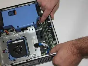
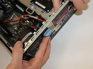
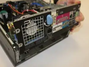
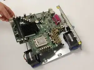
    • While rotating the case-opening knob, slide the motherboard tray away from the front of the computer.

  16. NBVsd2OW2luobDSE
    • Lift the motherboard from the rest of the computer case.

  17. XoB4eAcamBNEflp1
    • Remove two silver 6mm #2 Philips screws from the Hard Drive Stand.

  18. K3hTpurPuJgEsVkJ
    • Slide the Hard Drive Stand to left side.

    • Lift the stand, and disconnect the HDD fan power.

  19. tfIHtoGeNIqphYDs
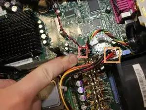
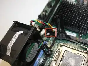
    • Unplug the cable that connects the chassis intrusion detection switch, distinguished by its red wires.

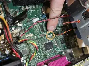
    • Unplug the cable that powers the hard drive, which has orange, red and yellow wires.

    • Make sure to press on the release tab while removing the connectors.

  20. 6HdWVGQK3KVDZO4Y
    • Disconnect the two fans from the motherboard.

  21. A4cLoCLjBtYMbK1g
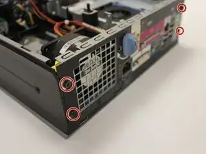
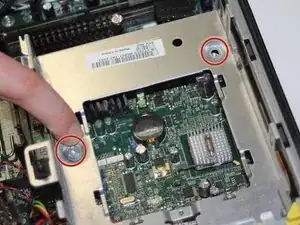
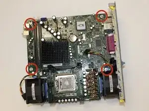
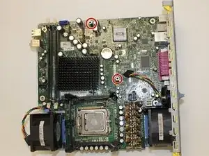
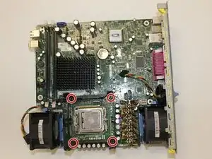
    • Remove the four silver 6mm #2 Philips screws holding the motherboard to the rear computer panel.

  22. roDCEcZthUHhDaBG
    • Remove the studs that support the Hard Drive Stand from the motherboard.

    • The studs can be removed by hand.

    • If studs can't be removed by hand a 6mm nut driver or spanner may be used.

  23. 1Gqh2lbAyXWnLthp
    • Remove the four black 9mm #2 Philips screws located on heat sink stand.

  24. aGqTwaWxSansg41r
    • The motherboard can now be removed from the remaining panel.

Conclusion

To reassemble your device, follow these instructions in reverse order.

donnavon

Member since: 02/09/14

707 Reputation

0 comments