Introduction
The voltage regulator board is an internal component and will require disassembly of the screwdriver casing. Due to disassembly of the casing, you will be required to use a few special tools listed in the outer casing replacement guide. Consult the outer casing replacement guide for instructions on removing the casing. Also, use caution when working on the screwdriver internally - always unplug the battery before replacing any components. This guide will also require a soldering iron and basic soldering skills for replacing the battery contact board. It is advised that you check all other components before replacing the voltage regulator board, as this is a last resort component to be replaced if screwdriver does not work.
-
-
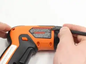
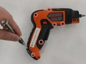
Remove all six of the 12-mm long case screws with a Philips #1 Screwdriver. These screws can be found on the side of the LI4000 with the "Warning" sticker.
-
-
-
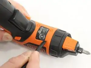
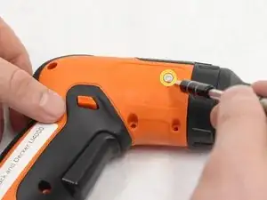
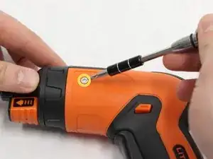
Remove the two screws that are 4-mm Hexagonal #2.5. These are very small case screws that can be found underneath the two stickers from Step 1.
-
-
-
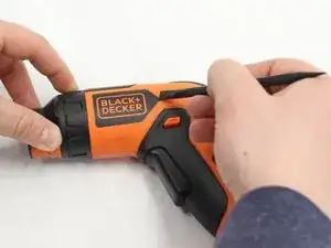
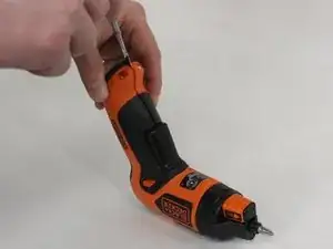
Pry on the seam as shown with a Spudger, in order to get the top casing loose.
-
Pull the two sides apart while making sure the side that you are removing is the one with all of the case screw holes.
-
-
-
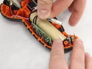
Locate the negative terminal of the battery.
-
Remove the negative (black) wire by pulling back gently.
-
-
-
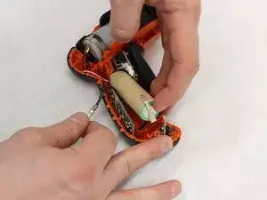
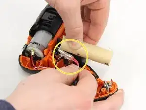
Gently pull up on the end of the battery closest to the negative terminal. Pulling the battery up should reveal the positive (red) wire located on the opposite end of the battery.
-
To free battery, gently pull back on the positive (red) wire.
-
-
-
Set battery aside in a safe place.
-
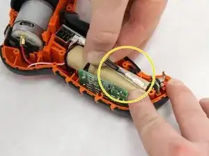
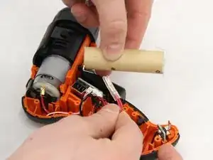
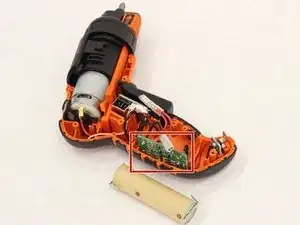
Locate the voltage regulator board near back midsection of the handle on the screwdriver.
-
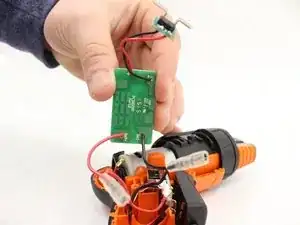
Slowly pull up on the voltage regulator board.
-
-
-
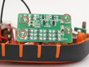
Locate the four soldering joints (two connected to battery contact board and two connected trigger/switch board).
-


To reassemble your device, follow these instructions in reverse order.