Introduction
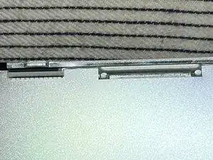
Thunderbolt Display uses an LG edge LED lit LCD Display (also 09-11 27" iMacs and 27" Cinema Displays). The LEDs are on the bottom edge of the display. There are 2 bars (left and right) Each bar has many LEDs and a 6 pin connector. Each pin drive several LEDs thus is the highest current flow / heat junction. The weak lead free solder gradually fails with thermal expansion/contraction cycling and increases resistance. PSU will compensate up to a point, then when the current is too high, PSU just shut down the backlight causing a dark display. I have even seen connector just fell off as solder points became completely detached.
Usually this problem starts manifesting itself with brighter settings only. Can work around by reduce brightness. Eventually, even the lowest brightness won't work anymore.
Made a PDF long ago to detail this repair. Largely duplicated in this guide but attached it here (at the end) for additional reference.
-
-
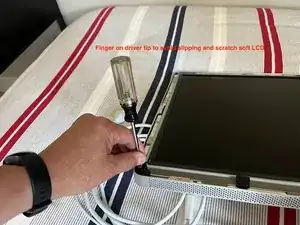
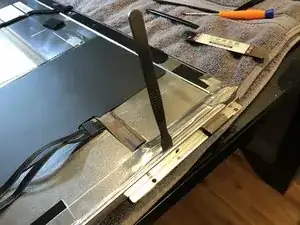
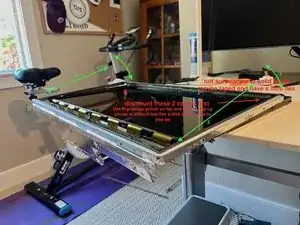
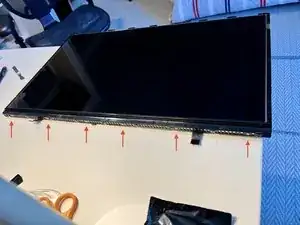
Follow LCD removal guide Additional tip is to put fingers over the tip of the T10 driver to prevent it from slipping off. LCD surface is very soft and will scratch instantly against any metal driver.
-
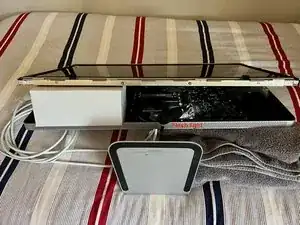
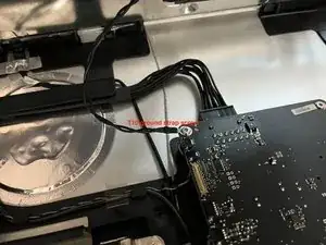
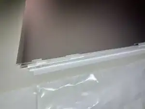
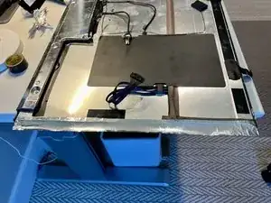
Good to use small box to hold up LCD will disconnecting 4x LCD cables (power, video, temp sensor, and ground wire) See next steps or more pics
-
Keep the 8x T-10 screws separate from the other T-10 removed later
-
-
-
Really strong magnets near the 8x LCD mounting screws. And screws can easily fall into the abyss of the iMac. A curved tweezer works well to assist in both removal and reinstall.
-
-
-
More pics on disconnecting LCD cables
-
With LCD propped up by a box, a small flashlight (plastic casing would be best) can help see the connectors.
-
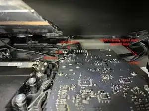
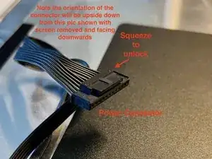
Power connector is the hardest as its under the main board so need to blind disconnect. First remove the clear tape that holds down the cable. Then feel by finger to find the connector, squeeze the lock and pull. See picture for reference (note the picture of the connector is removed and shown upside down for clarity)
-
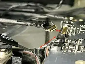
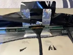
The video connector has a locking latch that must be unclipped. Picture shows a handle tape on this latch. Pull up on tape and unclip the latch before pulling out the connector.
-
After power, video, and 6pin connector are disconnected. Can tilt the LCD assembly higher (60-70 degrees so nearly vertical) to remove the T-10 ground screw with a driver.
-
-
-
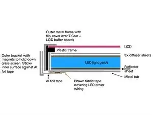
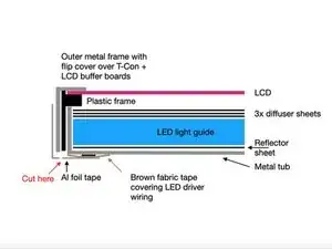
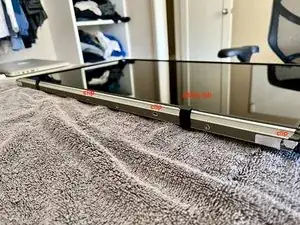
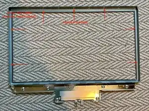
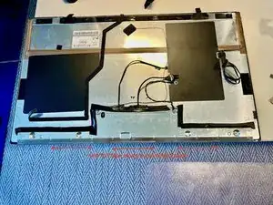
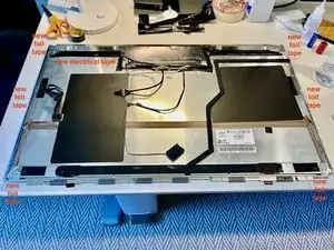
Here are the sandwiched layers of the LCD assembly along the 2 sides of the LCD assembly. It is quite involved and difficult. Consider wearing gloves to continue or if dislike gloves (sweaty) as there are many steps remaining. Need to clean LCD later with proper solution.
-
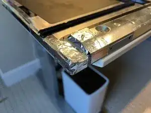
LED driver wires and brown fabric tape are only present on small sections of the sides
-
-
-
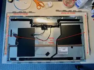
Remove 2 L shaped side brackets and 1 bottom bracket. Each bracket is held in by 4x T10. 2 side L bracket have sticky surfaces on the inside making it very difficult to pry off (use very thin metal spudger). Sticky surface is against the thin foil tape so it may scrape off some tape (its okay, need to peel it off anyways)
-
Note the picture shown with brackets removed has the foil tape already removed
-
-
-
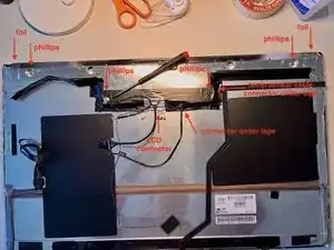
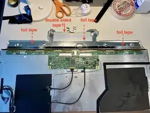
Peel off black tape surrounding the cover. Careful around the 3 connector regions (notes below) Peel off foil tape at the 2 ends of cover. Remove 4x phillips screws.
-
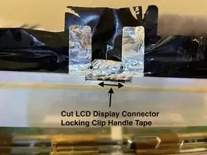
LCD connector is very difficult. Its a flip latch connector with a handle tape just like the other end of cable. The handle tape is stuck together with the cover tape in 3 layers of sticky pages. Be careful not to rip the LCD connector off the t-con board. Often need to cut handle tape. See more pic in next step for details
-
-
-
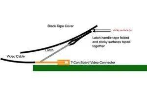
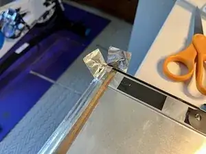
Latch handle tape is just a sticky tape folded together over the latch.
-
There are 3x sticky surfaces (cover tape, latch handle tape) all glued together. When pulling up cover tape, it will put pulling force on the LCD connector. Could rip the connector off the T-Con board if not careful.
-
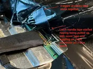
Pic shows handle tape already ripping despite caution when peeling the cover tape. Easiest is to just cut the handle tape once starting to be exposed.
-
-
-
When flipping up cover for the first time, there will be some resistance from the foil tape on the outside of the cover seam
-
-
-
Rotate up T-Con (pivot on flex cable side) and release it from sticky tape. Likely difficult first time to release the tape.
-
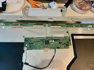
Unlatch t-con to buffer board flex on buffer board side. Wiggle t-con board gently to release flex from connector (likely difficult on first release)
-
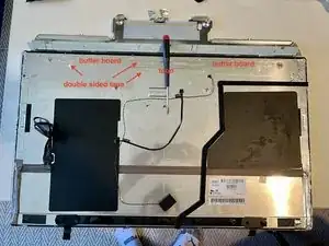
Flip up buffer board to release from sticky tape. Difficult first time to release the tape. Be gentle to avoid damaging the gold foil flex bonded between buffer board and LCD. Unrepairable without pro equipment if this foil flex bond is broken
-
After flipping up the buffer board. Gently put it back down to keep it secured against the double sided tape to get ready to remove the outer metal frame. We are releasing the buffer board first time here as later on will not have good orientation to the difficult first time release.
-
-
-
Takes awhile to peel off all the foil tape (where it says new foil tape in pic) on both sides.
-
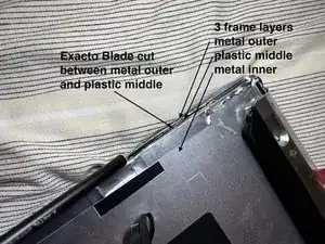
If you are a risk taker, can use an xacto knife to cut between outer metal frame and plastic frame. When near the brown tape region, careful not to cut it and the LED wires underneath.
-
-
-
Can use a razor blade to help remove tape along the sides. Avoid razor blade near the brown fabric tape region (has LED wires underneath) Fortunately, Al foil comes off pretty easy when over the brown fabric tape.
-
Lift up foam tape in a couple of places to peel off foil tape underneath.
-
-
-
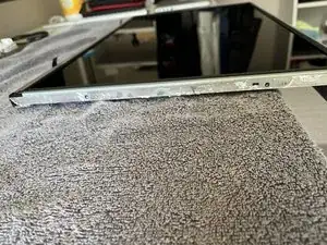
Note when outer metal frame is off, LCD will fall out if assembly is turned over so be very careful.
-
Peel back 2 black lifting tabs
-
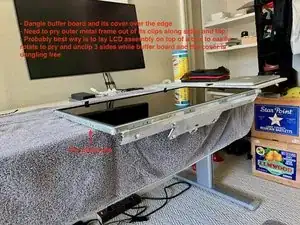
For first timer, probably best to sit LCD assembly on top of a box so the buffer boards and cover can dangle free while inserting a pry tool along the perimeter to unclip the outer metal frame. Box allows easy LCD rotation while working to unclip the 3 sides (2 sides and lifting tab side)
-
-
-
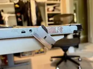
Start lifting the outer metal frame from the side with lifting tab. This is to avoid any scraping motion over the buffer board gold foil flex cable.
-
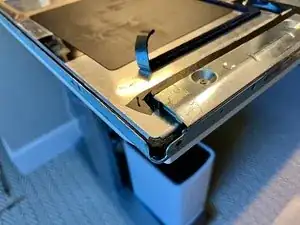
The corners on the lift tab side is slightly flexable. Probably need 2 pry tool on each side of the corner to release it. Be gentle as LCD glass is just under the outer metal frame. Luckily it sits in a plastic tub (see next steps pics) so should be safe from any prying tool
-
-
-
Lift up the small brown fabric tape on side of the LCD and the LCD the completely freed for removal
-
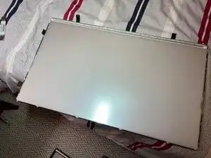
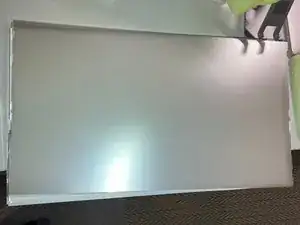
Prepare clean plastic liner on a flat surface. Suction cup lift LCD off (2 corners away from buffer boards first) and place LCD with its diffuser facing side onto the liner with buffer boards dangling over the edge. Avoid using anything with lint as a liner. The underside of the LCD facing diffusers require full disassembly to clean out any lint.
-
Remove the suction cups. Leaving suction cups on for long periods can leave a visible mark on the LCD when powered on (eventually heals but don't take a chance)
-
-
-
Remove 6x Phillips screws on lift tab side of the plastic frame
-
Pry and unclip the plastic frame
-
-
-
Prepare clean lint free liner to cover diffuser stack after removal. I use thin garbage can liner.
-
IMPORTANT : Any crimp/fold/damage to these sheets will show up on display so handle with care. Avoid any finger print on the diffuser sheet. It is okay to handle from bottom of the white reflector sheet thats facing the tub
-
I removal the whole stack (3x diffuser sheet, plexi glass like lightguide and the white reflect sheet on the bottom) I recall there are corners near the LED bar that can lift the whole stack (will confirm in future)
-
Put stack down with white reflector sheet on the bottom on a clean surface. Cover top diffuser sheet with lint free liner.
-
-
-
Do not remove the curved LED silver reflector bar (it is brittle and difficult) There is no need
-
Do not remove the LED bar. There are thermal transfer tape underneath that will be torn up. Not necessary
-
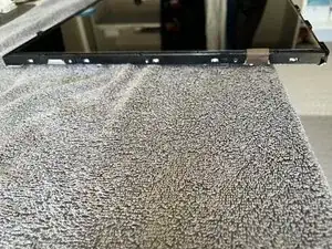
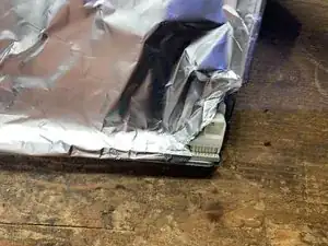
Cover connector region with Al foil to protect against heat. Wick off old lead free solder. Reflow with fresh leaded solder.
-
-
-
tub has notches to align all the diffuser sheets. Top sheet is near the top of the notch and easily float around. Make sure aligned properly before clipping on the plastic frame.
-
Take great care to not crimp any of the diffuser sheets when reclipping on the plastic frame
-
Make sure the brown fabric tape that will fold over edge of LCD is outside of the plastic frame
-
Install the 6x philips screws. Check prior picture for exact hole location. There are other holes for installing magnetic bracket. If use these holes, then can't install magnetic bracket later which require removing the fragile LCD again.
-
-
-
Make sure the diffuser sheet surface is clean and preferably kept clean during disassembly and no need to touch the surface. If need to clean, use mild proper cleaning solution (30% ISO, 70% distilled water mix) and micro fiber to wipe gently clean. Anything on the surface will be trapped under the LCD
-
Hang the edge where buffer boards will go over an edge. Suction cup and install the LCD by aligning the 2 corners opposite of the buffer board first. Gently sit LCD down into the plastic frame. Make sure it sits properly in the plastic frame guides
-
-
-
Insert the buffer board end first. Again, avoid any sliding motion over the gold buffer board to LCD flex cables.
-
Then clip in the corner opposite to the buffer board and clip in all 3 non buffer board sides.
-
Basically reverse of the motion for removal
-
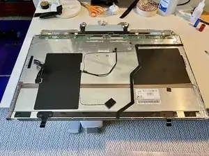
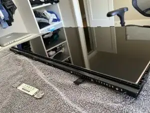
LCD is now secured in the outer metal frame and the assembly can be flipped over. Make sure its on a clean flat surface when LCD is facing down. It will not touch the surface. Outer metal frame has a foam bumper around the edge. This foam bumper can easily scrape and cut when rotating LCD assembly on edge of the table so becareful.
-
-
-
Screw holes for the cover are alignment posts for the buffer and t-con board.
-
Insert buffer board first
-
Insert T-Con flex into buffer board connector. Lock connector tab. Set T-Con down aligned and onto the sticky tape
-
Install all 3 cables (video, temperature sensor cable and the 3rd cable) Close the cover (make sure don't crimp the temp sensor cable) Reinstall cover screws.
-
-
-
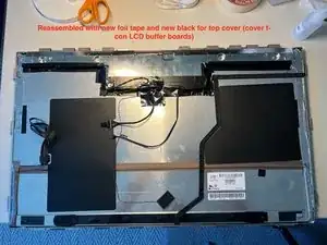
This is an important step to avoid thermally induced popping/clicking noises post assembly. The metal t-con buffer board cover is quite long, has a seam and is installed against the metal tub.
-
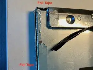
New Al foil tape over the 2 sides, all 4 corners, and both ends of the cover. Preferably clean off all the old tape
-
-
-
Remove and install new Al foil tape over cover seam. Some iMacs have tape over the entire seam rather than 3 segments shown in this pic.
-
-
-
The 2 L bracket likely got bent during the difficult removal. Bend as necessary to straighten.
-
Facing LCD glass down on a flat surface. Install brackets to ensure magnets are flush against the flat surface. Install Torx Screws. This is the alignment to ensure magnetic glass installation will be flush
-
On bottom straight bracket, clamp the 2x black lifting tab under the bracket. Tabs can easily break over their folds. Not a problem.
-


To reassemble your device, follow these instructions in reverse order.